PID Controller in Converter Design:
- In above diagram, Converter output voltage and current is monitored through ADC and it will be compared with desired value (reference). PID controller correct the error value and corresponding PWM pulse width will be adjusted to get desired output.
- When error zero or in desired range the PID controller will not adjust PWM pulse width.
Analog PID Controller:
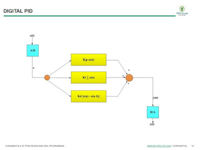
Digital PID Controller:
- Analog and digital PID controller concepts are discussed in text book. Check the theoretical backaround on this.
- Digital PID controller will be implemented inside the FPGA.
- Above Digital PID equations will be considered in programming for calculating Proptional, derivative and integrative errors.
Next Class we will be discussing the VHDL program
If you have any questions please email :miycircuits@gmail.com


No comments:
Post a Comment